 JTD-SP-GPS-0-xNX
JTD-SP-GPS-0-xNX

l 2 路 (JTD-SP-GPS-0-2NX) GPS 分配器是一種單輸入雙輸出 GPS 設備。該產品通常會發現來自主動式 GPS 屋頂天線的輸入在兩個接收 GPS 單元之間平均分配的應用。在這種情況下, 2 路 GPS 分路器可配置為將 DC 從 RF 輸出 (J1) 傳遞到天線輸入端口,以便為該端口上的主動式 GPS 天線。第二個射頻輸出 (J2) 將具有 200 歐姆直流負載以模擬天線直流連接到這些端口的任何接收器的電流消耗。
The 2 way (JTD-SP-GPS-0-2NX) GPS Splitter is a one‐input, two‐output GPS device. This product typically finds application where an input from an active GPS roof antenna is split evenly between two receiving GPS units. In this scenario, the 2 way GPS Splitter can be configured to pass DC from an RF output (J1) to the antenna input port in order to power an active GPS antenna on that port. The second RF output (J2) would feature a 200 Ohm DC load to simulate an antenna DC current draw for any receiver connected to those ports.
l 4 路 (JTD-SP-GPS-0-4NX) GPS 分配器是一種單輸入、四輸出 GPS 設備。該產品通常會發現來自主動式 GPS 屋頂天線的輸入在四個接收 GPS 單元之間平均分配的應用。在這種情況下, 4 路 GPS 分路器可配置為將 DC 從 RF 輸出 (J1) 傳遞到天線輸入端口,以便為該端口上的主動式 GPS 天線。第二、第三和第四個射頻輸出(J2、J3 和 J4)將具有 200 歐姆直流負載模擬連接到這些端口的任何接收器的天線直流電流消耗。
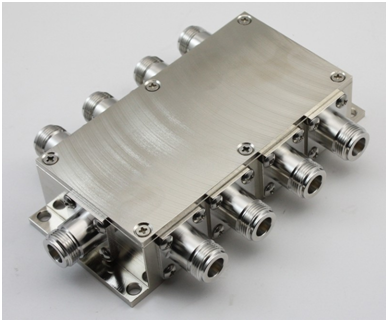
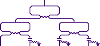
The 4 way (JTD-SP-GPS-0-4NX) GPS Splitter is a one‐input, four‐output GPS device. This product typically finds application where an input from an active GPS roof antenna is split evenly between four receiving GPS units. In this scenario, the 4 way GPS Splitter can be configured to pass DC from an RF output (J1) to the antenna input port in order to power an active GPS antenna on that port. The second, third and fourth RF outputs (J2,J3, & J4) would feature a 200 Ohm DC load to simulatean antenna DC current draw for any receiver connected to those ports.
l 8 路 (JTD-SP-GPS-0-8NX) GPS 分路器是一種單輸入、8輸出 GPS 設備。該產品通常會發現來自主動式 GPS 屋頂天線的輸入在八個接收 GPS 單元之間平均分配的應用。在這個在這種情況下,8 路 GPS 分路器可以配置為將 DC 從 RF 輸出 (J1) 傳遞到天線輸入端口,以便為該端口上的主動式 GPS 天線供電。其他輸出將具有 200 歐姆直流負載以模擬天線連接到這些端口的任何接收器的直流電流消耗。
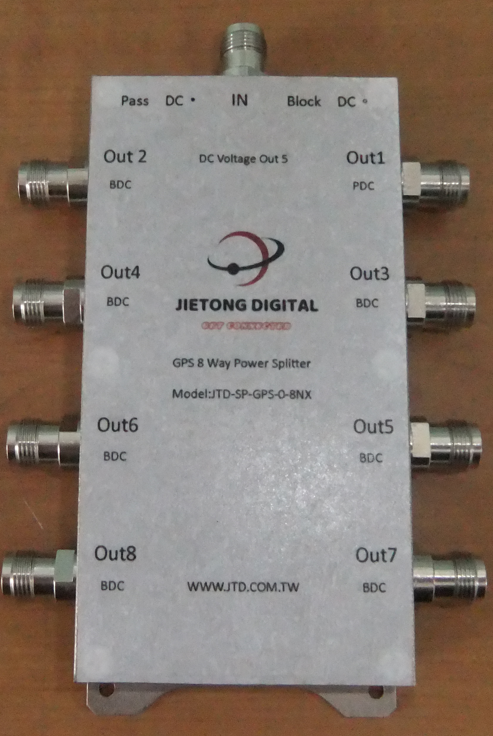
The 8 way (JTD-SP-GPS-0-8NX) GPS Splitter is a one‐input, eight‐output GPS device. This product typically finds application where an input from an active GPS roof antenna is split evenly between eight receiving GPS units. In this scenario, the 8 way GPS Splitter can be configured to pass DC from an RF output (J1) to the antenna input port in order to power an active GPS antenna on that port. The others outputs would feature a 200 Ohm DC load to simulate an antenna DC current draw for any receiver connected to those ports.
 為無線基礎設施應用設計
增益 0dB、21dB 和被動版本可用響應
全球定位系統:L1、L2、L2C、L5;
格洛納斯:G1,G2;
伽利略:L1,E1,E2,E5(E5a,E5b),E6;
北斗2:B1、B2、B3;
IRNSS:L1,L5;
全明星
高隔離度 > 30dB
Design For Wireless Infrastructure Applications Gain 0dB, 21dB And Passive Version Available Response For
GPS:L1,L2,L2C,L5;
Glonass:G1,G2; Galileo:L1,E1,E2,E5(E5a,E5b),E6; Beidou2:B1,B2,B3;
IRNSS:L1,L5;
Omni Star
High Isolations > 30dB


